
In this post, we want to give you a look at the detailed structure of our racks in various data centres.
Racks are generally equipped according to a particular pre-determined layout. We place great value on clearly organised cable management, to ensure that everything remains neatly arranged, even with a Full Rack that is fully equipped with servers. Every network and power cable used there is thus accordingly labelled with the rack unit and the switch port to be connected.
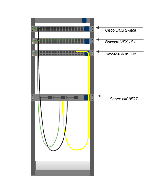
The cabling of our devices is convergent. When developing our rack layouts, all cable lengths of the network and power cables were individually measured to ensure the correct length for all installed servers. The example of cabling a server installed on rack unit 27 (U27) shows this quite well:
The server is connected
- to port 27 of the out-of-band management switch (OOB switch) using the black network cable
- to port 27 of the primary switch using the green network cable
- to port 27 of the secondary switch using the yellow network cable.
/verkabelungsmethodik.jpg) This cabling methodology is used for servers that are installed on units 02 through 27.
This cabling methodology is used for servers that are installed on units 02 through 27.
At the very top of the rack, on unit 47, there is an RJ45 patch panel and directly below it a cable termination (CT) for our fibre optic connections.
Two switches per rack from the brand “Brocade VDX 6740T” are responsible for the network connection of our servers. With 10 gigabits, these are directly connected via fibre to our aggregation devices. The connection of these two VDXs with each other is realised using a 40-gigabit copper cable; we operate the out-of-band management via a Cisco 2950-48-EI switch installed in the rack. All our servers installed in the rack have an Intel RMM4 module. This greatly facilitates remote management, allowing us, for example, to read out event logs, system information and sensor readings and use the remote power control function.
One cable manager and one blind screen is installed under each switch. Doing so allows the network cables connected to the respective switches to be properly laid to the servers according to rack layout. Our servers are supplied with power by two E3METER bus bars per rack, which are equipped with 36 C13 and six C19 plugs. These are installed to the side of the racks in front of the cross pieces. The servers are connected to the C13 plugs and the network devices to the C19 plugs on the bus bar. In order to ensure a redundant power supply, both bus bars are connected via a CEE plug to different power distributors (USV1 und USV2). The bus bars are also 3-phase and thus 11kW-redundant.
/rack_innen.jpg)
Our racks are divided into two segments: Managed and Root. This means that within these segments, the servers are used only for the respective product category. Each rack also has a partner rack. This is a rack that is equipped in exactly the same way, but does not stand in the same hot aisle. Since the racks are always connected to two different power distributors, any failure of a power sub-distributor does not result in a power outage. The partners racks are also used, for example, for our Managed Cluster – in this case, both setup servers are housed in two partner racks. Thanks to the partner racks, a high-availability setup can thus be realised even as a Root Server customer.
/setup-partnerrack.jpg) Sketch of partner rack setup with the connections to the power distributor
Sketch of partner rack setup with the connections to the power distributor
Our data centre team is very happy to help you with any questions you may have about our rack setups.
Fahrudin Izic works for nine.ch as an infrastructure officer and is responsible, among other things, for installing and cabling servers and switches in our data centres.


